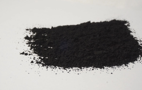
Silicon deposition inside Porous Carbon is one of the most scalable ways to manufacture Si/C composite powders—especially vapor-deposited silicon anodes where silane (SiH₄) is delivered as a gas and silicon forms in situ inside a Porous Carbon framework. The value proposition is clear: Porous Carbon supplies internal void space to buffer silicon’s volume change and a conductive skeleton to keep silicon electrically connected. Recent work demonstrates scalable silane CVD producing amorphous silicon nanodots embedded within porous hard carbon microspheres.
But there’s a catch that shows up in almost every sourcing and process-debugging search query: silicon does not automatically fill every pore uniformly. If the deposition is too fast at the outer surface, the entrance region can seal, starving the interior and limiting silicon loading. The deciding factor is rarely porosity alone. It is pore size distribution (PSD)—the mix of micro/meso/macro pores and the connectivity between them—that determines whether Porous Carbon for Silicon Deposition can achieve high loading and good uniformity—or it can fail early via pore blocking.
A modeling study of silane deposition into nanoporous carbon describes this as a coupled advection–diffusion–reaction problem and shows that pore size, surface area, pressure, flow rate, and temperature together control uniformity.
A recent Si/C pore-structure optimization paper reinforces the same message from a performance angle: carbon pore structure is a key (and still challenging) lever in Si/C design.
What you’ll get from this guide (aligned with common Google intent):
How PSD changes gas transport inside Porous Carbon
Why crust growth happens and how PSD makes it worse (or better)
A spec-ready checklist for selecting Porous Carbon for Silicon Deposition
Side-by-side product comparisons and a troubleshooting table designed for featured snippets
Why Porous Carbon is the go-to host for silicon deposition
The goal of silicon deposition is simple to state and hard to execute:
High silicon loading for energy density
High uniformity for stability, rate capability, and predictable swelling
A carbon host is attractive because it is conductive, chemically compatible, and can be engineered across pore scales. Porous Carbon adds one more essential feature: internal free volume. In designs like porous hard carbon microspheres, defects and internal pores can anchor silicon (as nanodots or thin deposits) and reduce agglomeration during cycling.
Commercial interest is also rising. A recent strategic report describes silicon-based anodes as approaching a turning point, with production expanding since 2024—pushing manufacturers toward materials and processes that scale (including consistent Porous Carbon feedstocks).
PSD beats porosity because it controls transport, reaction, and blocking
Two Porous Carbon batches can share the same total porosity and still behave very differently during silicon deposition, because PSD controls:
Transport resistance (how fast silane reaches internal surfaces)
Where silane is consumed first (entrance vs interior)
How quickly pore throats close (blocking dynamics)
A classic vapor infiltration study on porous carbon preforms for reaction-formed SiC (different end product, same infiltration physics) reported carbon preforms with porosity in the 35–67% range and pore sizes from roughly 0.03 to 2.58 μm, and emphasized that vapor infiltration can lead to deeper infiltration under suitable conditions.
That quantitative span matters: it tells you that the right PSD depends on how you deliver silicon—gas infiltration behaves differently when pores are tens of nanometers versus microns.
Transport regimes inside Porous Carbon: molecular diffusion vs Knudsen diffusion
Gas transport through Porous Carbon is not one mechanism. It shifts with pore size:
In larger pores, molecular diffusion and viscous flow dominate.
In smaller pores, Knudsen diffusion becomes important.
A ScienceDirect engineering overview defines pore diffusion as transport influenced by pore length/diameter/tortuosity, with molecular diffusion in macro/mesopores and Knudsen diffusion in micropores.
This matters for Porous Carbon for Silicon Deposition because the transport regime determines whether silane can reach deep internal surfaces before it reacts.
A practical caution comes from an activated-carbon support study on Si deposition: under atmospheric pressure CVD, diffusion effects into micro/mesopores were described as minimal, implying that measured pores may not be usable pores under certain conditions.
Where does silicon deposit first? A deposition-front picture
Most deposition profiles in Porous Carbon can be understood with a deposition-front concept:
Silane concentration is highest at the outer surface.
Silicon nucleates at the easiest-to-reach surfaces (outer surface + large entrances).
Growing silicon narrows pore throats, increasing transport resistance.
Concentration gradients steepen; the interior becomes starved.
If entrances seal, interior loading plateaus.
The nanoporous-carbon silane model explicitly studies how pore size, surface area, pressure, flow rate, and temperature influence uniformity and filling fraction—useful for translating PSD into process targets.
The crust growth failure mode and why PSD triggers it
When users search low silicon loading, a common structural root cause is crust growth: rapid deposition at the surface that blocks further infiltration. PSD makes crust growth more likely when Porous Carbon has:
Narrow pore throats (bottlenecks)
Extremely high surface area concentrated near entrances
Poor connectivity (dead ends)
You can think of PSD as the geometry of access. If access is fragile, early silicon growth changes the geometry (throat narrowing) and shuts the door.
Data-focused specs for Porous Carbon for Silicon Deposition
Below is a spec-first translation of PSD into measurable procurement language. This is designed to be copied into an RFQ or internal spec sheet.
What to measure (and what it predicts)
| Spec item | Typical measurement | What it predicts for Porous Carbon for Silicon Deposition |
| Pore size distribution (PSD) | N₂ adsorption (meso), CO₂ adsorption (micro), mercury porosimetry (macro) | Infiltration depth, uniformity, blocking resistance |
| Total pore volume | Adsorption/porosimetry | Upper bound for internal silicon storage |
| Specific surface area (SSA) | BET | Nucleation density + silane consumption rate |
| Connectivity / tortuosity | Imaging or transport-derived metrics | Gradient strength and risk of isolated pores |
| Particle size distribution | Laser diffraction | Diffusion length inside each particle |
A state of the art characterization review notes that micropore PSD can be challenging and that diffusion problems in very narrow micropores can affect characterization—important when you are correlating PSD data with deposition outcomes.
A practical PSD target: hierarchical pores
A repeatable target concept is hierarchical porosity in Porous Carbon:
Macropores: fast delivery pathways (highways)
Mesopores: main deposition/storage volume (streets)
Controlled micropores: surface chemistry and nucleation (alleys), but not so dominant that transport collapses
This aligns with recent Si/C literature emphasizing pore-structure optimization as a key performance lever.
Product comparison: which Porous Carbon architecture fits which deposition goal?
People rarely search PSD theory for fun—they want to pick a material. Here’s a comparison centered on PSD and deposition behavior.
| Porous Carbon option | PSD tendencies | Strengths for silicon deposition | Main risks | Good fit |
| Activated carbon | Micropore-heavy + small mesopores | High nucleation density; potentially high loading | Entrance depletion; limited usable micro/mesopores at certain conditions | Tuned low-pressure or slower-rate CVD |
| Porous hard carbon microspheres | Mixed mesopores + defects | Scalable silane CVD demonstrated with embedded Si nanodots | Needs PSD control to avoid outer-shell growth | High-throughput Si/C powders |
| Macroporous frameworks | Connected macrochannels + mesoporous walls | Fast access, lower blocking probability | Less internal surface unless walls are engineered | Fast-charge designs |
| CNT-based scaffolds | More external surface than true internal pores | Easy gas access; surface-controlled deposition | Lower internal storage vs true porous hosts | Conductive networks / surface Si |
One activated-carbon support study found increasing porosity improved dispersion-related behavior but that excessively high porosity reduced contact area and harmed stability—useful context when deciding how “open” your Porous Carbon should be.
PSD scenario table: what different Porous Carbon PSD shapes usually produce
If you only remember one thing: Porous Carbon PSD is a map of access. Different PSD shapes tend to create different silicon deposition profiles in Porous Carbon for Silicon Deposition.
| PSD scenario in Porous Carbon | What the pores look like | Typical deposition outcome | What buyers should ask for |
| Micropore-dominant Porous Carbon | Many <2 nm pores; very high SSA | Fast silane consumption near entrances; low deep fill; higher blocking risk | Add more mesopore volume; verify micropore fraction |
| Narrow mesopore peak Porous Carbon | Mostly one pore size band (e.g., 5–20 nm) | Can be uniform at the right rate; can still block if throats are narrow | Ask for connectivity indicators; specify process window |
| Hierarchical Porous Carbon | Macro access + meso storage + some micro | Best chance of high loading + uniformity; more forgiving | Request full PSD curve (not just BET); set QC limits |
| Macropore-heavy Porous Carbon | Many >50 nm / micron pores | Great access; may underutilize volume unless walls add mesopores | Ask for mesoporous wall structure + pore volume |
This table is not a substitute for experiments, but it is a useful first-pass filter when comparing two Porous Carbon datasheets. It is also aligned with the core mechanisms described in silane deposition modeling (transport + reaction + geometry) and in recent Si/C pore-structure optimization discussions.
Mini back-of-the-envelope data analysis for Porous Carbon selection
A common purchasing comparison is: Both materials have similar BET—why does one fill better? BET alone can hide whether surface area is located in accessible mesopores or trapped micropores in Porous Carbon. To make comparisons more data-driven, ask suppliers to report:
Mesopore volume (cm³/g) and its fraction of total pore volume for Porous Carbon
Micropore volume (cm³/g) and its fraction for Porous Carbon
PSD curve method (N₂, CO₂, combined) to ensure apples-to-apples across Porous Carbon lots
Then compute a simple ratio you can track lot-to-lot:
Higher AVR usually indicates more usable storage and transport in Porous Carbon for Silicon Deposition, especially when your process is not optimized for deep micropore infiltration. This practical perspective matches experimental notes that micro/mesopore diffusion can be limited under certain CVD conditions and underscores why Porous Carbon measurement methods matter.
A practical Porous Carbon uniformity scorecard (for RFQs and scale-up)
To keep teams aligned, rate each candidate Porous Carbon on a 1–5 scale and compare side-by-side:
PSD fit (Does the Porous Carbon show hierarchical access + storage?)
Particle size fit (Is Porous Carbon particle size compatible with your diffusion length?)
Strength/attrition (Will Porous Carbon generate fines that change effective PSD?)
Lot consistency (Does Porous Carbon supplier provide SPC/QC trends on PSD and pore volume?)
Process match (Is your pressure/temperature window realistic for this Porous Carbon?)
This scorecard approach is especially relevant as micro-sized CVD-derived Si–C anodes gain attention for economic viability: when you scale, you need Porous Carbon that is forgiving and repeatable, not just high surface area.
Process knobs that interact with Porous Carbon PSD
PSD selection is only half the job. Your reactor settings can make the same Porous Carbon behave differently.
Pressure
At atmospheric pressure, diffusion limitations can reduce the contribution of micro/mesopores in activated carbon supports during Si CVD, which tends to favor more accessible pore networks or adjusted process conditions.
Temperature and silane partial pressure
Higher temperature and higher silane partial pressure usually increase deposition rate—but can reduce penetration depth by consuming silane near entrances. Broader silane CVD literature discusses diffusion limitations and scale-up issues (including fluidized beds), reinforcing that kinetics must match the pore network you chose.
Flow and residence time
Too low a flow can create strong depletion gradients; too high a flow can increase undesired homogeneous reactions/fines in some silane processes, a known reactor-design challenge.
For Porous Carbon for Silicon Deposition, validate uniformity under the real hydrodynamics you plan to scale.
2025–2026 trends: why Porous Carbon for Silicon Deposition is getting more industrial
Fresh trends matter because they shape what customers and procurement teams ask for.
A 2025 review highlights micro-sized CVD-derived Si–C anodes fabricated into porous carbon scaffolds, emphasizing improved economic viability—exactly where batch-to-batch PSD control in Porous Carbon becomes central.
Recent work on amorphous silicon nanodots embedded in porous hard carbon microspheres via scalable silane CVD shows how Porous Carbon design is being translated into manufacturable powders.
Industry reporting frames silicon anodes as scaling since 2024, increasing the need for consistent suppliers of Porous Carbon with controlled PSD and robust QC.
Buyer-ready checklist for Porous Carbon (copy/paste)
Use this when quoting or qualifying Porous Carbon for Silicon Deposition:
Declare the deposition route (tube furnace, rotary, fluidized bed, etc.).
Declare the chemistry (silane-only vs co-pyrolysis into porous scaffolds).
Require a PSD measurement stack (N₂ + CO₂ adsorption; macro porosimetry if needed).
Specify functional PSD targets: macro access + meso storage + controlled micro chemistry.
Set QC limits for PSD, pore volume, SSA, and particle size distribution (lot-to-lot consistency).
Ask for mechanical strength / attrition (fines change effective PSD and deposition behavior).
Quick spec language you can paste (Porous Carbon)
If you need one paragraph to align purchasing, R&D, and production, here is a compact spec sentence that intentionally repeats Porous Carbon so it survives copy/paste between teams:
Supplier shall provide Porous Carbon with documented PSD (N₂ + CO₂) and controlled pore volume for silicon infiltration.
Porous Carbon shall exhibit hierarchical access (macro/meso connectivity) to support uniform silane penetration during Porous Carbon for Silicon Deposition.
Lot-to-lot Porous Carbon variation in PSD, pore volume, and SSA shall be controlled within agreed limits.
Porous Carbon particle size distribution and mechanical strength shall be suitable for the target reactor to minimize fines and preserve Porous Carbon PSD during handling.
Any change to Porous Carbon raw materials or activation/carbonization conditions must trigger PSD requalification for Porous Carbon for Silicon Deposition.
Used well, this keeps Porous Carbon selection and Porous Carbon process tuning from drifting apart during scale-up.
In practice, Porous Carbon selection is Porous Carbon engineering: Porous Carbon PSD, Porous Carbon connectivity, and Porous Carbon consistency.
Troubleshooting: symptom → PSD cause → fix
| Symptom in Porous Carbon for Silicon Deposition | PSD-linked cause | Material-side fix | Process-side fix |
| Low silicon loading | Entrance-limited transport; pore blocking | Increase connected meso/macro pores | Lower deposition rate; staged infiltration |
| Outer-shell silicon | Too much entrance surface area / bottlenecks | More hierarchical PSD | Lower SiH₄ partial pressure; pulse/step |
| Batch inconsistency | PSD variation between lots | Tighten supplier QC | Improve gas distribution/mixing |
| Fast capacity fade | Poor balance of contact vs void | Optimize PSD + morphology | Electrode formulation adjustments |
Conclusion
For silicon deposition, Porous Carbon is simultaneously the transport network, the reaction surface, and the expansion buffer. The latest modeling and Si/C pore-structure optimization work reinforce that PSD engineering is a manufacturing control lever, not an academic detail.
If you want uniform silicon loading, treat PSD as the contract between your reactor kinetics and your Porous Carbon for Silicon Deposition material spec—and control it with the same seriousness as particle size, purity, and yield.


